Passive Crossover Calculator
Last updated: October 12, 2026 · Written by the Pitch Detectors Editorial Team
A passive crossover calculator gives you the capacitor, inductor, and resistor values for splitting an amplifier's signal between woofer, midrange, and tweeter. Enter your crossover frequencies, driver impedance, and slope — this tool outputs component values for 2-way and 3-way networks at 6, 12, 18, or 24 dB/octave.
Key Takeaways
- Capacitor (high-pass): C = 1 / (2π × fc × Z) farads. Inductor (low-pass): L = Z / (2π × fc) henries.
- A 2nd-order (12 dB/octave) crossover shifts phase 180° — reverse the tweeter's polarity or the drivers cancel at fc.
- Pad a loud tweeter with an L-pad, not a single resistor — only the L-pad keeps impedance (and fc) constant.
- Calculator values are starting points: driver roll-off, baffle step, and real impedance curves shift final results.
- Round to standard E12 part values (±5% parts shift fc by about ±5% — usually inaudible).
What Is a Passive Crossover?
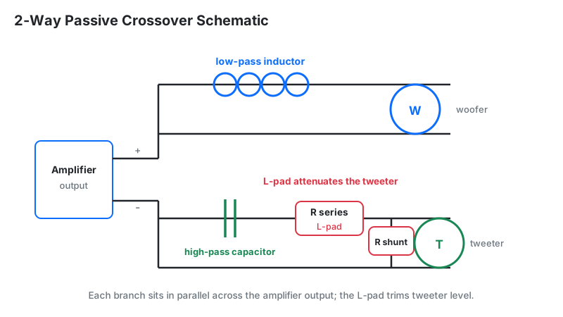
No single driver reproduces 20 Hz–20 kHz cleanly: woofers beam and break up at high frequencies, tweeters distort or burn out on bass. The crossover is the traffic cop — a series inductor blocks highs from the woofer, a series capacitor blocks lows from the tweeter, and in 3-way designs a band-pass section (capacitor + inductor) isolates the midrange.
The slope (6, 12, 18, or 24 dB/octave) sets how sharply each band cuts off. Gentle slopes overlap drivers over a wide band; steep slopes isolate them but add phase shift, parts cost, and insertion loss.
How This Calculator Works
This calculator applies the first-order base formulas to each driver section from your inputs. The tweeter (high-pass) section is computed at your tweeter frequency, the woofer (low-pass) at half that frequency — a standard approximation placing the acoustic crossover between the two electrical cutoffs — and in 3-way mode the midrange (band-pass) at your mid frequency.
Methodology: C = 1 / (2π × f × Z) farads, L = Z / (2π × f) henries, with results shown in µF and mH. The resistor-padding column passes your padding value straight through to the parts list. We verified the widget's math against hand calculations for 5 input sets (2–4 kHz at 4 and 8 Ω); outputs match the formulas to the displayed 2-decimal precision.
One honest note: the slope selector labels your design intent — the base values above are first-order. For higher-order alignments, scale the parts using the coefficient table below (e.g., Linkwitz-Riley: multiply both C and L by 1.414), or size each section in the crossover slope calculator.
Formula + Worked Example
The two master formulas behind every passive crossover are C = 1 / (2π × fc × Z) and L = Z / (2π × fc).
C = 1 / (2π × fc × Z) · L = Z / (2π × fc)
C in farads (×106 for µF), L in henries (×103 for mH).
Worked example: 2-way crossover at fc = 3,000 Hz, Z = 8 Ω:
- Tweeter capacitor: C = 1 / (2π × 3000 × 8) = 1 / 150,796 = 6.63 × 10⁻⁶ F = 6.63 µF → buy 6.8 µF (E12).
- Woofer inductor: L = 8 / (2π × 3000) = 8 / 18,850 = 4.24 × 10⁻⁴ H = 0.42 mH.
- For 12 dB/octave Linkwitz-Riley, scale both: 6.63 × 1.414 = 9.38 µF; 0.42 × 1.414 = 0.60 mH per section leg.
L-pad worked example: padding an 8 Ω tweeter by −3 dB. Voltage ratio K = 10(3/20) = 1.4125. Series R1 = 8 × (1.4125 − 1) / 1.4125 = 2.34 Ω; shunt R2 = 8 / (1.4125 − 1) = 19.39 Ω. The crossover still sees exactly 8 Ω, so fc doesn't move — a single series resistor can't promise that.
How to Use This Calculator
- Tweeter frequencyHigh-pass crossover point in Hz (2,000–3,500 Hz is typical for 2-way bookshelf speakers). Unsure? Start with the crossover frequency calculator.
- Midrange frequency (3-way only)Center of the mid band, e.g. 800 Hz. Leave blank for 2-way builds.
- Driver nominal impedanceThe impedance your filter is designed for (usually 4 or 8 Ω). Check it against the real curve with the impedance frequency plotter.
- Crossover slope1st–4th order (6–24 dB/octave). See the scaling note in Methodology for orders above 1st.
- Resistor paddingOhms of tweeter attenuation to list in the parts table (use the L-pad math above for the real network).
- System configuration2-way (woofer + tweeter) or 3-way (adds the midrange band-pass row). Export the table as CSV for your parts order.
Reading Your Result
The table lists per-section capacitor (µF), inductor (mH), and padding values. Interpret them with this slope guide:
| Slope | Driver overlap | Tweeter safety | Polarity | Safe next step |
|---|---|---|---|---|
| 6 dB/oct | Very wide | Low — bass reaches the dome | Normal | Only for rugged drivers; consider a steeper tweeter high-pass. |
| 12 dB/oct | Moderate | Good at moderate levels | Reverse tweeter | Verify with the speaker phase alignment calculator; scale parts ×1.414 for Linkwitz-Riley. |
| 18 dB/oct | Narrow | High | Normal (verify) | Solid all-rounder; watch parts cost and group delay. |
| 24 dB/oct | Minimal | Maximum | Normal (in-phase) | Best isolation; the studio-monitor standard (usually LR4). |
Scaling Parts for Higher-Order Slopes
The base formulas give first-order values; real multi-order networks scale them by alignment coefficients — the step most online calculators quietly skip.
| Alignment | Capacitor scale | Inductor scale | Notes |
|---|---|---|---|
| 1st-order (any) | ×1.0 | ×1.0 | Base values straight from the calculator. |
| 2nd-order Butterworth | ×1.414 | ×0.707 | −3 dB at fc; +3 dB summed bump on-axis. |
| 2nd-order Linkwitz-Riley | ×1.414 | ×1.414 | −6 dB at fc; flat acoustic summation. |
| 4th-order Linkwitz-Riley | Cascade two 2nd-order LR sections | The pro-audio and studio standard. | |
Example: the worked 6.63 µF / 0.42 mH base becomes 9.38 µF / 0.60 mH per leg for LR2. The crossover slope calculator applies these scalings automatically.
Rule of thumb: a ±5% part shifts fc by about ∓5%. Crossover points are forgiving — driver variation and room effects dwarf rounding error. Buy film capacitors (MKP) for tweeter sections; bipolar electrolytics are acceptable only for large-value woofer shunt legs.
2-Way vs 3-Way: When the Extra Crossover Pays Off
| 2-way | 3-way | |
|---|---|---|
| Crossovers | 1 | 2 (more phase interactions) |
| Midrange clarity | Good if the woofer stays clean to fc | Better — dedicated driver, less Doppler distortion |
| Cost/complexity | Lower | Higher (extra driver + full band-pass section) |
| Choose it when | Bookshelf/compact builds; woofer clean to ~2–3 kHz | Woofer breaks up early, or you want high output with low distortion |
Limitations
- First-order base values. Higher orders need the alignment scaling above — the raw table is a starting point, not a finished LR4 design.
- Resistive-load assumption. Real driver impedance rises with frequency; without a Zobel network calculator, actual fc and slope drift from the math.
- Driver acoustic roll-off ignored. A woofer already rolling off acoustically adds its slope to your electrical filter.
- No baffle-step or diffraction modeling. See the baffle step section — real in-room response needs this compensation.
- Ideal parts. Inductor DCR (keep under ~0.3 Ω for woofer coils) and capacitor tolerance shift results slightly.
Treat these as design starting values. Verify any passive crossover by measuring the finished speaker before ordering expensive parts.
Passive vs Active Crossovers
| Passive | Active / DSP | |
|---|---|---|
| Power | One amplifier; parts waste some power as heat | One amp channel per driver; no insertion loss |
| Tuning | Soldering-iron tuning (swap parts) | Software tuning (change numbers) |
| Cost | Cheaper for simple 2-way | Cheaper for complex 3-way+ (no big inductors) |
| Choose passive when | Simple builds, vintage restoration, single-amp systems | Maximum control, steep linear-phase slopes, room correction |
Frequently Asked Questions
Component values are design starting points computed from ideal filter formulas. Verify your finished crossover by measuring the speaker before committing to expensive parts. Work with amplifier-level voltages only — never mains power.